Iranian Classification Society Rules

< Previous | Contents | Next >
CHAPTER 5 STABILITY AND SUBDIVISION
101. General
1. For the purpose of this chapter, unless expressly defined otherwise, the following definitions apply:
(1) "Worst intended conditions" means the specified environmental conditions within which the in- tended operation of the craft is provided for in the certification of the craft. This should take into account parameters such as the worst conditions of wind force allowable, wave height (including unfavourable combinations of length and direction of waves), minimum air temper- ature, visibility and depth of water for safe operation and such other parameters as the Administration may require in considering the type of craft in the area of operation.
(2) "Down flooding point" means any opening through which flooding of the spaces which comprise the reserved buoyancy could take place while the craft is in the intact or damage condition and
heels to an angle past the angle of equilibrium.
(3) "Permeability" of a space means the percentage of the volume of that space which can be occu- pied by water.
(4) "Watertight" in relation to a structure means capable of preventing the passage of water through
the structure in any direction under the head of water likely to occur in the intact or damage condition.
(5) "Weathertight" means that water will not penetrate into the craft in any wind and wave con- ditions up to those specified as critical design conditions.
(6) "Design altitude in calm water" means the altitude when WIG craft is operated as actual speed in ground effect mode under calm water.
(7) "Worst design altitude" means the altitude when WIG craft is operated in ground effect mode under the maximum significant wave height, limited point of operation.
(8) "Amphibian mode" is the special short-term mode of amphibian WIG craft when it is mainly
supported by a static air cushion and moves slowly above a surface other than water.
(9) "Displacement mode" means the regime, whether at rest or in motion, where the weight of the craft is fully or predominantly supported by hydrostatic forces.
(10) "Transitional mode" denotes the transient mode from the displacement mode to the step-taxi mode and vice versa.
(11) "Planing mode" denotes the mode of steady which the craft's weight is supported mainly by
(12) "Take off/landing mode" denotes the transient
fect mode and vice versa.
state operation of a craft on water surface by hydro-dynamic forces.
mode from the planing mode to the ground ef-
(13) "Ground effect mode" is the main steady state operational mode of flying the WIG craft in ground effect.
(14) "Fly-over mode" denotes increase of the flying altitude for WIG craft of types B and C with- in a limited period, which exceeds the vertical extent of the ground effect but does not exceed
the minimal safe altitude for an aircraft prescribed by ICAO provisions.
2. References for the stability in the displacement mode under the intact and damaged condition should be submitted to verify stability of WIG craft. Moreover, references indicating the character- istic and installation for stability to land safely despite troubles of some equipment under the worst intended condition should be submitted.
3. Account should be taken of the effect of icing in all stability calculations where icing may occur.
If there is an ice breaker, that should be considered for stability calculations.
102. Buoyancy
1. All WIG ships should have a sufficient reserve of buoyancy to meet the intact and damage stabil- ity requirements. The Society may require a larger reserve of buoyancy to permit the craft to oper- ate in any of its intended modes. And arrangements should be provided for checking the watertight integrity of those compartments. Where the buoyancy are be calculated, watertight compartments be-
low the draught and watertight or weathertight compartments above the draught in.
2. Where entry of water into structures above the datum as defined in 102. 1 (3) influence the stability and buoyancy of the craft, such structures should be:
should be included
would significantly
![]()
Guidance for WIG ships(Wing-In-Ground Effect Ships) 2012 11
![]()
(1) of adequate strength to maintain the weathertight integrity and fitted with weathertight closing appliances; or
(2) provided with adequate drainage arrangements; or
(3) an equivalent combination of both measures.
The means of closing openings in the boundaries of weathertight structures should be such as to maintain weathertight integrity in all operational conditions.
103. Intact stability
1. General
(1) It should be shown by calculations and/or by trials that in all operational modes and load cases within its operational restrictions a craft will return or can be readily made to safely return to the initial position of draught/altitude, heel and trim when displaced during roll, pitch, yaw or heave motions or when subjected to a transitory force or moment associated with such motions.
(2) Suitable precautions of arrangement, equipment or operational procedures should be taken against the craft developing dangerous altitudes, yawing, inclinations or loss of stability subsequent to a collision with a submerged or floating object in displacement, transitional, take-off/landing, plan- ing and surface effects modes, particularly in modes where any part of the craft or its appen- dages is submerged.
(3) When turning in calm water the inner angle of heel should not:
(A) induce instability in the craft;
(B) exceed the angle at which the wing makes contact with the water surface necessitating cor- rective control action when in the ground effect mode in calm water at the design altitude;
and
(C) exceed the angle at which the skeg makes contact with the water surface when the craft is in the ground effect mode.
2. Intact stability in the displacement mode
(1) Craft should have sufficient stability in calm water in all possible and permitted conditions of cargo stowage and with uncontrolled passenger movement so that a residual freeboard of 0.1 m is maintained in way of the datum described in 102. 1 (3) and all parts of fixed airfoils ex- cluding flaps and ailerons.
(2) The angle of heel under the combined action of heeling moments due to passenger crowding according to 108. 1 (1) and the greater of the moments due to wind and turning being de- termined experimentally should not exceed 8 degrees or the angle of entrance of the wing into the water, whichever is the less.
(3) The stability of WIG craft, which is difficult to apply (1) and (2), should be verified by the re- sults of trials conducted with the craft itself.
3. Stability in the transitional and take off/landing mode
The maintenance of sufficient stability should be verified by trials and documented in the opera- tional procedures in the transitional and take off/landing mode up to the worst intended condition, if the change of WIG craft mode is not concerned with stability. The angle of horizontal heel un- der combined action of heeling moments due to passenger crowding according to 108. 1 (1) should not exceed 80 % of the wing surface angle in the transitional mode and 50 % in the take off/land- ing mode.
4. Stability in ground effect mode
(1) Under the worst intended conditions, which are in both of bow wave and bow wind or stern wave and stern wind, the maximum heeling angle should not exceed 90 % of the angle between a part of WIG ship and surface of the ocean when WIG ship having load condition of mini- mum stability turns along the minimum radius. This angle can be determined according to the
flight altitude corresponding to the worst
(2) In case WIG ship is specially designed
design altitude.
and constructed to be touched a part of hull with the
surface of sea in order to reduce the a turning radius in ground effect mode despite (1), a sta- bility on operation should be verified by a trial.
(3) In case WIG ship includes automatic stabilizing equipment controlling the vertical, horizontal and longitudinal direction motion, WIG ship should have an enough stability to be operated
safely while automatic stabilizing equipment is not used as the same way.
![]()
12 Guidance for WIG ships(Wing-In-Ground Effect Ships) 2012
![]()
(4) Under the worst intended conditions, healing angle derived from the combination of more influ- ential factor between effect by passenger concentration of 108. 1 (1) and wind pressure or high speed turn should not exceed the angle that skeg and perpendicular plate of edge of the wing get into the water. the combined healing angle can be determined by a calculation or trial.
5. Stability in fly-over mode
The stability in fly-over mode should be verified by a calculation and test considering significant factors, such as a speed of craft, a distance with the subject, a height and size of the subject, etc.
6. The stability of WIG craft, which is difficult to apply 103. 2 to 5, should be verified by the re- sults of trials conducted with the craft itself.
7. Stability verification
(1) If the craft is fitted with a system for directing sprays of air engines under a wing or other craft structures to create a static air cushion or for other purposes, then the effect of that sys- tem on craft stability should be taken into account.
(2) For a craft which is designed and certificated to be capable from the displacement mode wholly or partly to mount to a gentle slope shore (and to come down backwards) and to operate in
amphibian mode, the maintenance of verified by trials and documented in
satisfactory stability during such manoeuvres should be the operational procedures, including transit through the
wave breaking zone in all conditions up to the worst allowable conditions for those manoeuvres.
(3) Validation of stability in calm water should be verified by trails.
104. WIG craft weather criteria
1. Craft operation, depending on the operational modes, should be restricted by the worst intended conditions and critical design conditions specified according to the results of trials conducted with the craft itself or with one of the craft of a series of identical craft.
2. In the displacement mode of operation, stability is considered to be sufficient if the following con- ditions are observed when the dynamically applied heeling moment BĐ due to the beam wind pres- sure (in the loading condition with least reserves of stability and subjected to the critical design
conditions) is equal or less than the capsizing moment Bᾏ,
BĐ P Bᾏ or Å Ņ BǼ Õ BĐ Q ÌǾL
3. The heeling moments due to the wind pressure should be taken as constant during the whole peri- od of heeling and determined as follows:
The heeling moment BĐ(kNm) in the displacement mode of operation is calculated as follows:
BĐ Ņ LǾLLÌ ČĐ AĐ Ě ᾚ
where:
ČĐ :
AĐ :
Ě :
ᾚ :
wind pressure (NÕmĪ)
windage area (the projected lateral area of the portion of the craft above the acting water- line) (mĪ )
the windage area lever equal to the vertical distance to the centre of windage from the centre of the projected lateral area of the portion of the craft below the plane of the act- ing waterline (m)
streamline factor, ᾚ < 1, determined by model tests in a wind tunnel (ᾚ = 1 if such data are lacking)
The value of ČĐ should be determined according to Table 5.1 for wind force corresponding to the critical design conditions. This wind force should be at least one Beaufort scale number higher than
![]()
Guidance for WIG ships(Wing-In-Ground Effect Ships) 2012 13
![]()
that corresponding to the worst intended conditions.
Table 5.1 Wind pressure ČĐ (Pascal)
Wind force | Vertical distance between the centre of the projected lateral area of the WIG craft and the sea surface in m | |||||||
Beaufort Scale | m/s | 1 | 2 | 3 | 4 | 5 | 6 | 7 < |
2 | 5 | 15 | 20 | 25 | 25 | 30 | 30 | 35 |
3 | 7 | 50 | 60 | 65 | 70 | 75 | 80 | 85 |
4 | 9 | 95 | 120 | 135 | 145 | 150 | 160 | 165 |
5 | 12 | 155 | 195 | 220 | 235 | 250 | 265 | 275 |
6 | 15 | 240 | 300 | 335 | 360 | 385 | 400 | 415 |
7 | 19 | 435 | 545 | 605 | 655 | 700 | 730 | 750 |
8 | 23 | 705 | 875 | 970 | 1050 | 1115 | 1170 | 1230 |
4. The amplitude of rolling in the displacement mode is to be determined according to 6 or equiv- alent method with propulsion and stability equipment inoperative.
5. The recommended scheme for determination of the capsizing moment, BǼ , in the displacement mode of operation is given in 104. 6 (1) and (2). For this purpose, the angle of flooding should be taken as the lowest angle of heel corresponding to residual freeboard of 300 mm below:
(1) the lower window sill;
(2) the upper edge of the coaming of the outside entry door; or
(3) other points of flooding.
6. The minimum capsizing moments, BǼ , in the static and dynamic stability curves taking rolling
displacement mode is to be into account.
determined from the
(1) When the static stability curve is used, BǼ is determined by equating the areas under curves of the capsizing and righting moments (or levers) taking rolling into account, as
the in-
dicated by Fig 5.1, where ßĚ is the amplitude of roll and Bᾟ is a line abscissa axis such that the shaded areas S1 and S2 are equal.
BǼ = OM, if the scale of ordinates represents moments,
BǼ = OM × displacement, if the scale of ordinates represents levers.
drawn parallel to
the
(2) When the dynamic stability curve is used, first an auxiliary point A should be determined. For this purpose the amplitude of heeling is plotted to the right along the abscissa axis and a point A' is found (see Fig 5.2). A line AA' is drawn parallel to the abscissa axis equal to the dou- ble amplitude of heeling (AA' = 2ßĚ ) and the required auxiliary point A is found. A tangent AC to the dynamic stability curve is to be drawn. From the point A the line AB is drawn par- allel to the abscissa axis and equal to 1 radian (57.3°). From the point B a perpendicular is drawn to intersect with the tangent in point E. The distance BE is equal to the capsizing mo- ment if measured along the ordinate axis of the dynamic stability curve. If, however, the dy- namic stability levers are plotted along this axis, BE is then the capsizing lever. In this case
the capsizing moment sponding displacement
BǼ is determined by multiplication of ordinate BE (in m) by the corre- in tons
BǼ Ņ ĶǾKÌ∆ÆĂ (kNm)
(3) The amplitude of rolling ßĚ is determined by means of model and full-scale tests in irregular seas as a maximum amplitude of rolling of 50 oscillations of a craft travelling at 90° to the
wave direction in sea state for
the worst design condition. If such data are lacking, the ampli-
![]()
14 Guidance for WIG ships(Wing-In-Ground Effect Ships) 2012
![]()
tude is assumed to be equal to 15°.
(4) The effectiveness of the stability curves should be limited to the angle of flooding.
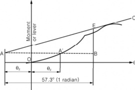
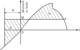
Fig 5.1 Static stability curve Fig 5.2 Dynamic stability curve
105. Buoyancy and stability in the displacement mode following damage
1. For the purpose of damage stability calculations, the volume and surface permeability should follows:
be as
Space | Permeability |
Appropriated to cargo or stores | 60 |
Occupied by accommodation | 95 |
Occupied by machinery | 85 |
Intended for liquids | 0 to 95* |
Appropriated for cargo vehicles | 90 |
Void space | 95 |
* Whichever results in severer condition.
Permeability may be also determined by direct calculation.
2. Low-density foam or other media may be used to provide buoyancy in void spaces, if necessary.
Any proposed medium should be:
(1) of closed-cell form or otherwise impervious to water absorption;
(2) structurally stable under service conditions;
(3) chemically inert in relation to structural materials with which it is in contact or other substances with which the medium is likely to be in contact; and
(4) properly secured in place and easily removable for inspection of the void spaces.
3. The possible damages should be assumed to consider all of the reason causing the damage, except that the total loss condition as a part of hull is divided. The craft following damage should have sufficient buoyancy and positive stability in sill water to simultaneously ensure that:
(1) after flooding ceased and a state of equilibrium reached, the final waterline is not to be less than 300 mm below the level of the openings;
(2) the angle of inclination of the craft from the horizontal does not normally exceed 10° in any direction. However, where this is clearly impractical, angles of inclination up to 15° immediately after damage but reducing to 10° within 15 min. may be permitted provided that efficient
non-slip deck surface and suitable holding points, e.g., holes, bars, etc., are provided;
(3) there is a positive freeboard from the damage waterline to survival craft embarkation positions;
(4) any flooding of passenger compartments or escape routes which might occur will not sig- nificantly impede the evacuation of passengers;
(5) essential emergency equipment, emergency radios, power supplies and public address systems
needed for organizing the evacuation remain accessible and operational.
![]()
Guidance for WIG ships(Wing-In-Ground Effect Ships) 2012 15
![]()
106. Inclining and stability information
1. Every craft, on completion of construction should be inclined and the elements of its stability are to be determined. Alternatively, the mass and centre of gravity of the craft may be determined by weighing methods. When it is not possible to accurately determine the craft's vertical centre of gravity by either of these methods, it may be determined by accurate calculation.
2. A report of each weighing, inclining or lightweight survey carried out in accordance with this chap- ter and of the calculation therefrom of the light-ship condition particulars should be submitted to this society for approval, together with a copy for their retention. The approved report should be placed on board and incorporated when adding or amending.
3. The information should include particulars appropriate to the craft and reflect the craft's loading conditions and modes of operation. All watertight and weathertight structures included in the cross curves of stability and the critical down flooding points and angles should be identified.
107. Marking of the draft mark and the design waterline
1. The draft mark should clearly be marked on the bow and stern. If it is difficult to read the draft mark, installation directing the draft of the bow and stern should be attached.
2. The design waterline should clearly be marked amidships on the craft's outer sides.
108. Passenger regulations
1. Passenger regulation in the displacement mode should be satisfied with as follows:
(1) Where compliance with this chapter requires consideration of the effects of passenger weight, the following information should be used:
(A) Each passenger has a mass of 75 kg.
(B) Vertical centre of gravity of seated passengers is 0.3 m above seat.
(C) Passengers and luggages should be considered to be in the space normally at their disposal.
(D) Passengers should be distributed on available deck areas towards one side of the craft on the decks where shoulder stations are located and in such a way that they produce the most
adverse heeling moment.
(2) The stability of the craft should be verified according to the assumptions of paragraph (1) for each of the following loading conditions:
(A) with full number of passengers and cargo and full provisions on board craft
(B) with full number of passengers and cargo and with 10 % of provisions
(C) without passengers and cargo and with 10 % of provisions.
(3) The stability of the craft should be verified under the loading condition described in paragraph
(2) (B) but with 50 % of the passengers located in their seats on one side from the craft centre line. The remaining passengers should be located in their seats and/or passageways and other spaces not allocated to individual passengers so as to result in maximum heeling moment to- wards the side on which passengers remain seated. ![]()
![]()
16 Guidance for WIG ships(Wing-In-Ground Effect Ships) 2012
![]()